Mosfet-Amp: Amplifier with field-effect transistors at the output stage
The Hi-Fi amplifier with MOSFET transistor output stage has excellent performance and sound. This amplifier is quite easy to make yourself. You can buy a printed circuit board of the amplifier; you can buy an assembled amplifier board. Or you can make the circuit board and solder everything yourself.
The amplifier has combined negative feedback (otherwise known as hybrid feedback, Mad Feedback), so its output impedance can be non-zero and reach tens of ohms (it is set during the assembling of the amplifier). Sometimes amplifiers with increased output impedance sound better than “ordinary” amplifiers, the sound becomes similar to “good tube sound”.
What is combined negative feedback?
The combined negative feedback works with two signals simultaneously. It is the speaker voltage and the speaker current. ” Traditional” NFB uses the voltage on the loudspeaker only. The current is not used in any way. The combined NFB also uses the current in the loudspeaker. The result is more accurate loudspeaker control. And the output impedance of the amplifier is increased.
Increasing the output impedance of an amplifier is exactly equivalent to putting a resistor in series between the amplifier and the loudspeaker. But if you put a real resistor in series between the amplifier and the loudspeaker, there will be a loss of power on that resistor. With a combined voltage and current NFB, there is no power loss.
Increasing the output impedance of the amplifier has certain effects:
- Loudspeaker cables have less effect on the sound.
- The quality factor of the loudspeaker is increased. In some cases, too much Q-factor makes the sound worse. For a subwoofer in a closed box, increasing the Q factor can result in better bass reproduction. Sometimes it is useful to increase the quality factor of a powerful speaker in this way.
- Distortion on many loudspeakers is reduced. Because the effect of the non-linear inductance of the loudspeaker on its current is reduced.
- Sometimes it appears as if the sound is not coming out of the loudspeaker, but arises in space.
- If the output impedance of the amplifier is too high, the loudspeaker crossovers are disturbed. This results in a distortion of their amplitude-frequency response.
- If the output impedance of the amplifier is too high, the quality factor of the loudspeaker becomes excessive. This will cause the loudspeaker to ” hum “.
If the NFB current value is too high, the output impedance of the amplifier will also be too high. In order to keep the output impedance from increasing more than necessary, the NFB current value should be small. The optimum output impedance is usually between 0.1 ohms and 6 ohms.
Some say that the sound of an amplifier with increased output impedance resembles a tube sound.
You can calculate the combined NFB using the program combinos-engl. There is also an example of the effect of the output impedance of the amplifier on the amplitude-frequency response of the a closed box subwoofer.
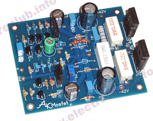
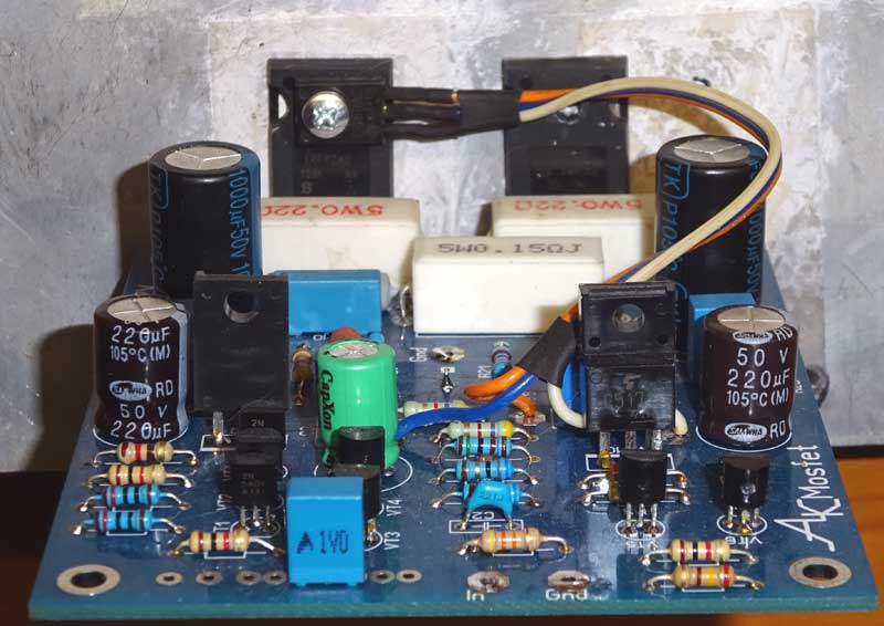
Figure 1 shows the assembled amplifier circuit board. This is an experimental case, which was the basis for a small redesign of the circuit.
Warning! This picture shows the experimental version of the amplifier. Some parts of the amplifier have different ratings from those in the schematic, and the transistor VT9 is not mounted at all.
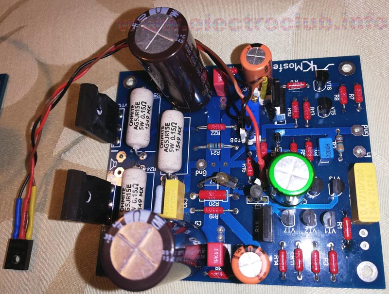
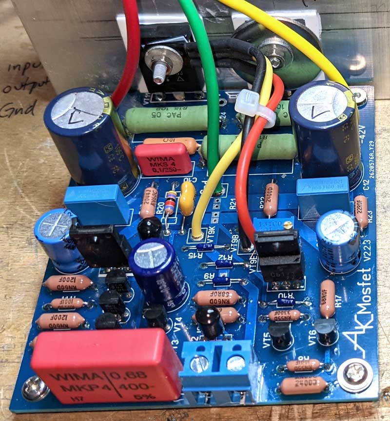
This amplifier is repeated many times and gets good reviews. Figure 2 shows Hi-Fi MOSFET amplifiers assembled in Denmark and USA.
What is the difference between this amplifier and the amplifier on the TDA7293 chip? The amplifier on the chip is simpler (that is what the chip is for), but weaker. This amplifier has a higher maximum output power and better sound quality, because its basic parameters are better.
Remember that the output impedance of this amplifier can be between 0…20 ohms. You choose the desired output impedance value before making it.
Basic parameters of the amplifier
They say that the technical parameters of the amplifier are not necessary. They don’t. Despite all the assertions that your amplifier’s sound is peerless, you need to know the real capabilities of your amplifier. The basic parameters of an amplifier are as follows:
- Gain = 32 times = 30 dB.
- Maximum output power in a 4 ohm load 150 W.
- Maximum output power in an 8 Ohm load 120 W.
- THD at 1kHz at 60W output power not exceeding 0.005%.
- IMD measured by the SMPTE method at 60 Hz and 7 kHz with an amplitude ratio of 4:1 not exceeding 0.005%.
- IMD measured at 18 and 19 kHz with an amplitude ratio of 1:1 not exceeding 0,005%.
- Output voltage slew rate not less than 15 V/µs.
- Output impedance is 0…20 ohms.
The meaning of these parameters
Gain is set by the NFB value. If the gain is too low, the amplifier will be ” silent “. If the gain is too high, it means that the NFB is too small, therefore the distortion will increase. Gain = 30 dB is optimal. With this amplifier you should not reduce the gain less than 25 times, because the amplifier might lose stability.
The frequency response slope at the extreme frequencies of the working range is less than the hearing resolution at these frequencies. So no one will hear the drop in signal level.
The maximum output power depends on the power supply, so in reality it may be less. The numbers specified are the maximum that can be obtained from the amplifier.
Distortion coefficients indicate the amount of distortion. By definition, distortion is the difference between what you get at the output and what you put at the input. The distortion of this amplifier is very small, so we get exactly the signal in the loudspeaker that we put into the input. Different tests allow us to evaluate the performance of the amplifier from different angles.
As for the frequency range and slew rate of the output voltage. Very often these figures are used for advertising purposes – the more the better. Right up to the loss of common sense. For example, you buy a car. And you are offered two variants. The first car has a maximum speed of 260 km/h, the second – 590 km/h. Certainly, you will choose the second – it is faster, isn’t it? Or will you think, whether such maximum speed is necessary? It is the same with the speed parameters of the amplifier.
Limiting the ultra-low frequencies will prevent the loudspeaker from being overloaded by infrasound, which can occur, for example, when playing crooked vinyl LPs. Limiting the high frequencies will firstly reduce the penetration of possible interference. Secondly, it will eliminate the appearance of dynamic distortion arising from the use of NFB, and creating an unpleasant “transistor sound”.
Amplifier distortions
The measurements were made under real operating conditions of the amplifier.
Fig. 2a shows the THD amplitude-frequency response. The horizontal axis shows the frequency of the test tone, which was put to the input of the amplifier. During the measurements we used a 24-bit bit rate and a sampling rate of 192 kHz. Therefore, harmonics up to 90 kHz were taken into account. This is very important in order to correctly measure the THD at high frequencies.
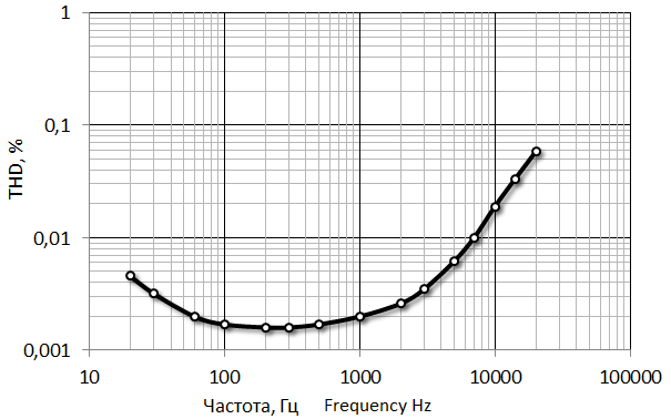
When it is written in the technical parameters of the amplifier: “THD in the range from 20 Hz to 20 kHz”, it does not always mean that the measurements are correct. Very often, in order to get nice advertising figures, they measure only those harmonics whose frequency is in the range from 20 Hz to 20 kHz. In this case the range 20 Hz to 20 kHz does not mean the frequency range of the test signal, but the range in which the harmonics are measured to calculate the THD.
For example, the frequency of the test signal is 1 kHz. If you measure harmonics with frequencies up to 20 kHz, the result is correct, because 20 harmonics with frequencies of 2 kHz, 3 kHz, 4 kHz and so on up to 20 kHz are taken into account. The measurement result may contain 20 harmonics, which is more than the amplifier actually generates.
If the frequency of the test tone is 10 kHz and the harmonics whose frequency is in the range up to 20 kHz are measured, then the result will be wrong. In the range up to 20 kHz only the second harmonic will be taken into account, the frequency of which is equal to 2x10kHz=20 kHz. The other harmonics with higher frequency will not be taken into account. Therefore, the harmonics with numbers 3, 4, 5, 6 and so on, produced by the amplifier, will not be included in the THD measurement result and the result will be incorrect. But the THD measured in this way will have a small value, very convenient for advertising.
In my measurements with a test signal frequency of 10 kHz it is possible to account for 9 harmonics. At the test signal frequency of 16 kHz the first 5 harmonics were included in the results. And when measuring at 20 kHz, 4 harmonics were taken into account. This is quite honest, because the amplifier generates noticeably 4-5 harmonics. As a result, the THD was measured correctly at all frequencies of the test signal.
Fig. 2b shows the distortion spectrum at 1 kHz. As you can see, it contains only the first three harmonics, the rest are below the measurement threshold (measurements were made at 24-bit, so all values above -120 dB are correct). Such a narrow distortion spectrum has a good effect on the sound quality, as a result there is no unpleasant “transistor sound” in the amplifier completely.
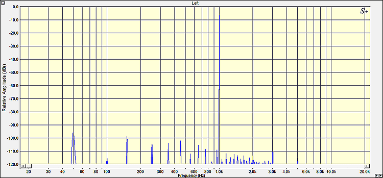
Fig. 2c shows the IMD spectrum with test frequencies of 18 and 19 kHz at an amplitude ratio of 1:1. This is one of the toughest tests to evaluate the linearity of the amplifier at high frequencies. It is important because at higher frequencies the NFB value decreases significantly. The test allows you to detect nonlinearity and/or poor high-frequency properties of the amplifier. As can be seen in Fig. 5, the difference frequency of 1 kHz has a vanishingly small value, which indicates a high linearity of the amplifier. The number of “side frequencies”, differing from the test frequency by the value of 1 kHz is also small and their amplitudes are small. This indicates that the distortion spectrum remains narrow (“soft”) even at high frequencies.
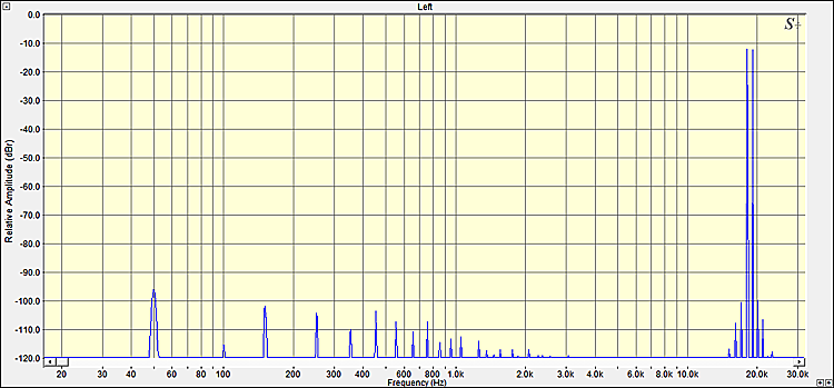
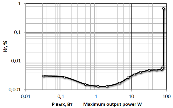
Fig. 2d shows the dependence of the harmonic coefficient at a frequency of 1 kHz and a load of 4 ohms on the output power. An 80 watt power supply was used. It should not be forgotten that the maximum output power of the amplifier depends on its power supply.
The measurement results show that in terms of distortion this amplifier is not only as good as some expensive and famous industrial amplifiers, but surpasses them.
Amplifier circuit
A circuit of the amplifier is shown in Figure 3.
Warning! The capacitance of capacitors C1 and C2 depends on the desired amplitude-frequency response and the amplifier’s operating conditions, so it may differ from the ones indicated in the diagram. To find out how to choose the capacitance of these capacitors, see below.
The resistor R21 is used to set the desired output impedance of the amplifier. So you choose the resistance of the resistor R21 on the basis of how much output impedance you want the amplifier to have. With the specified value of R21 = 20 kOhm, the output impedance of the amplifier is 0.5 ohms.
To choose the resistance of the resistor R21, see below.
If you do not need the increased output impedance of the amplifier, then do not install resistor R21 at all, and replace resistor R27 with a wire jumper. In this case the damping factor of the amplifier will be about 100.
This amplifier does not contain any complicated things. Therefore, even a beginner can assemble the amplifier with his own hands.
BOM List In English
Description of the amplifier circuit
The amplifier circuit is built according to the Lin topology. The input differential stage on transistors VT3 and VT4 is loaded on the current mirror VT1 and VT2.This provides maximum gain, symmetry and speed of output voltage slew rate. Resistors R5 and R6 in the emitters of the differential stage transistors increase the linearity of the stage and its overload capability. And they also reduce the influence of unequal transistors. The use of a current source VT5, VT6 as compared to a resistor, which is sometimes used in this place, reduces the level of intermodulation distortion. The emitter follower VT7 increases the gain.The transistor VT9 provides thermal stabilization of the output transistors VT11, VT12.
The R1C2 circuit is a filter that suppresses possible high-frequency interference. Don’t be idealistic – high-frequency interference will come into the amplifier, and this filter is the last bastion in their way. The capacity of capacitor C2 is given for the case when there is no volume control on the input of the amplifier. If a volume control potentiometer is installed at the input of the amplifier, the capacitor C2 should have a different capacitance, which depends on the resistance of the potentiometer. See below for the capacitance selection of C2.
The C7 capacitor performs two functions simultaneously, both of which are very useful:
- it “speeds up” the feedback.
- it limits the upper operating frequency of the amplifier. That is, the amplifier only works up to 80 kHz, not because the circuitry or parts are bad or slow. Without the C7 capacitor, the upper boundary frequency of the amplifier is about 600 kHz. That is, the amplifier itself is fast. But the amplifier is switched to an LPF circuit, so that at high frequencies, the depth of the NFB is increased, and the gain is reduced.This both reduces THD at high frequencies, and saves the amplifier from dynamic distortion.
But there are complexities in this application of the capacitor, so I cannot recommend it for absolutely all amplifiers.
The increased output impedance is created by a combined negative feedback, which uses both voltage and current. The voltage feedback is taken from the output of the amplifier and fed through resistor R20 to its inverting input. Current feedback is taken from the current sense R27 and fed to the inverting input via resistor R21. The somewhat unusual wiring of R9C4 is used to keep the offset of the amplifier as small as possible.
About the amplifier
Amplitude-frequency response of the amplifier
In the early days of audio engineering, it was a challenge to get the frequency range of an amplifier equal to the hearing range. A flat frequency response of 150 Hz to 6 kHz was a great achievement. And another amplifier with a frequency range of 100 Hz to 10 kHz was considered better and actually sounded better. So in those days, the frequency range of an amplifier was one of its most important parameters. An amplifier’s wide frequency range was a major accomplishment and was a source of justifiable pride, and was invariably listed in the specifications.
In the 21st century, the frequency range of any amplifier is automatically wider than 20 Hz…20 kHz. This parameter has become irrelevant, and it is not even always specified. Why am I talking about it?
It is not a problem for modern technology to make an amplifier with a frequency range from 0Hz (i.e. DC) to 1MHz. But why? Do you need a car with maximum speed of 550 km/h for real trips? ![]() In fact, all the talk about the need for an extra wide frequency range amplifier is an advertising and marketing gimmick.
In fact, all the talk about the need for an extra wide frequency range amplifier is an advertising and marketing gimmick.
What is important is this. If the amplifier itself is not able to reproduce frequencies below 20 Hz and above 20 kHz, then it is a bad amplifier. But to get such a bad amplifier, you have to make it on purpose. A modern “purely ordinary” but well-designed amplifier has a very wide frequency range. And this frequency range we limit artificially!
The most important thing is to limit the frequency range of the amplifier in a way that does not degrade the performance of the amplifier, for example, not to make it “slow”.
What is the purpose of limiting the frequency range of an amplifier?
- To avoid letting infrasound and ultrasound into the speakers, which are not designed to handle a signal of these frequencies and will not work well. And their poor performance will also affect the playback of sound frequencies. How will play the speakers, whose speakers are overloaded on the linear travel of the cone with infrasound? Terrible!
- To prevent these harmful frequencies from passing to the listener.
- It is impossible to remove harmful infrasound and ultrasound frequencies from the signal completely. These frequencies (since they are harmful, they are interference) can only be attenuated to one degree or another. But, though attenuated, they will come to the input of the amplifier. And if the interference enters the amplifier, it will cause an overload of the amplifier, because it is not designed to work with such frequencies. This overload will disturb the amplifier and the amplifier will distort the sound signal. If you limit the ultrasonic and infrasound noise, however, overloading will not occur and the sound will not be distorted.
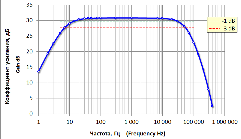
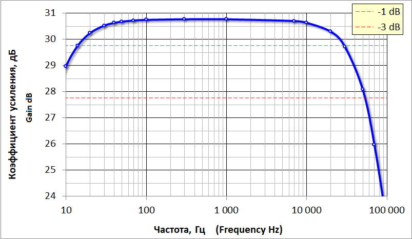
It is from such considerations that the AFR of this amplifier is formed. The AFR of the amplifier is shown in full in figure 4, and in figure 5 in an enlarged form.
The same figures show lines showing the levels:
-1 dB (green). At high and low frequencies, the sensitivity of hearing is such that a decrease in volume by 1 dB is not audible. That is, this is the conventional boundary of “even volume”.
-3 dB (red). This level determines the cutoff frequency of the amplifier, and therefore the technical frequency range.
So, for my proposed frequency response (it can be changed):
- “technical” frequency range at -3 dB level is 7 Hz … 50 kHz.
- The “auditory” frequency range (“equal loudness”) in level -1 dB is 14 Hz … 28 kHz. This value of the lower cut-off frequency is chosen so that the amplifier can be used for subwoofers.
The roll-off of the AFC at 20 Hz and at 20 kHz is about 0,5 dB.
If desired, the lower cutoff frequency can be increased. This is useful for speakers operating from 40 Hz and above.
How high frequency is this amplifier really?
In Figure 6, the blue line shows the AFR that I intentionally generated for this amplifier in the high-frequency region. The red line is the response that the amplifier would have had if I had not intentionally cut off the high frequencies. Then the -1dB cutoff frequency would be about 330kHz and the -3dB cutoff frequency would be about 600kHz. That is, the amplifier itself operates up to a frequency of 600 kHz.
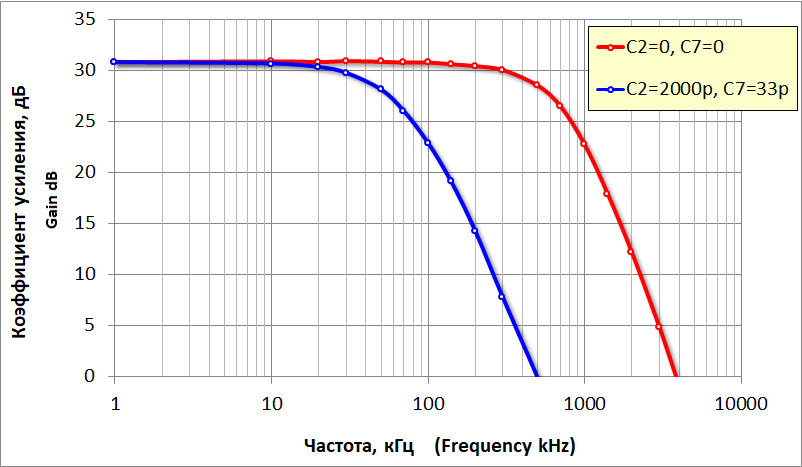
Besides limiting the ultrasonic gain, correction of the amplifier’s frequency response at high frequencies increases the depth of the negative feedback, which increases its linearity and reduces distortion.
The gain of the amplifier is about 30 times (about 30 dB) and depends on the parameters of the feedback circuit, which sets its output impedance. You can use the combinOS program (Russian and English versions) to calculate the parameters of the feedback circuit, as well as the gain for a given output impedance of the amplifier.
Amplifier output slew rate
Another important amplifier characteristic is the maximum slew rate of the output voltage. It characterizes the ability to obtain high-frequency signals of large amplitude at the output of the amplifier. If the maximum output slew rate is too low, it can cause dynamic distortion in an amplifier with deep feedback. This results in a very unpleasant “transistor” sound. So I measured the maximum slew rate of the output voltage while turning off all frequency correction of the amplifier (the capacitor C3, of course, was left in place).
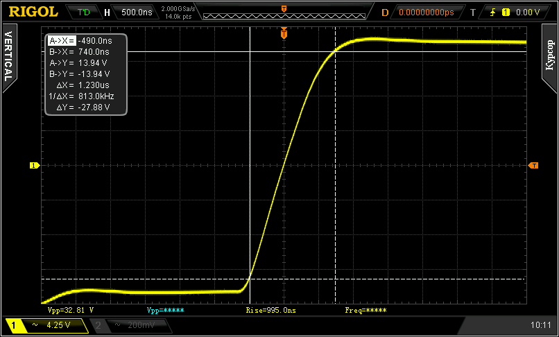
Figure 7 shows an example of this amplifier reproducing a 100 kHz square wave signal with an amplitude of about ±15 volts (yellow line). The blue line is the input signal, which is a near perfect meander.
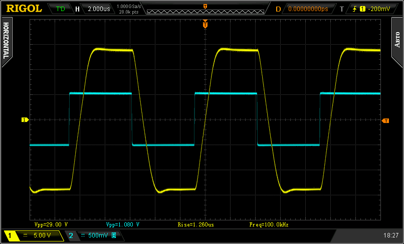
The oscillogram in Figure 7 clearly shows that the transient process of the amplifier is quite “beautiful”, there are no large spikes, much less oscillations. Such a transient process is characteristic for a 60…65 degree phase margin, which is optimal for amplifiers with deep feedback. The output voltage slightly lags behind the input voltage due to the phase shift at high frequencies. The output signal is rather rectangular, so it has frequencies of 100 kHz, 300 kHz, 500 kHz, 700 kHz, etc., which are many times higher than the audio ones, but they work out fine.
The oscillogram (Fig.8) gives the possibility to estimate the maximum slew rate of the output voltage rise:
I made a slight error with the upper reference point when measuring. If I had done it right, the number showing slew rate would have been even higher. But I was too lazy to redo it.
The maximum slew rate measured on a rectangular signal is a very good advertising parameter, because this method of measurement gives the highest number. But in the real operation of the amplifier such a situation in principle should not arise: with such a signal all stages of the amplifier are overloaded and the negative feedback does not work at all. If you try to playback the sound with the amplifier in this mode, the sound will be just terrible.
My aim is not to get a nice advertising number, but to find the maximum slew rate of the output voltage of the amplifier in such mode, which is acceptable in real operation. When dynamic distortion is just beginning to occur, there is little or no feedback, and the sound is virtually undistorted. This will be the speed limit, just below which the amplifier works fine and above which the distortion begins.
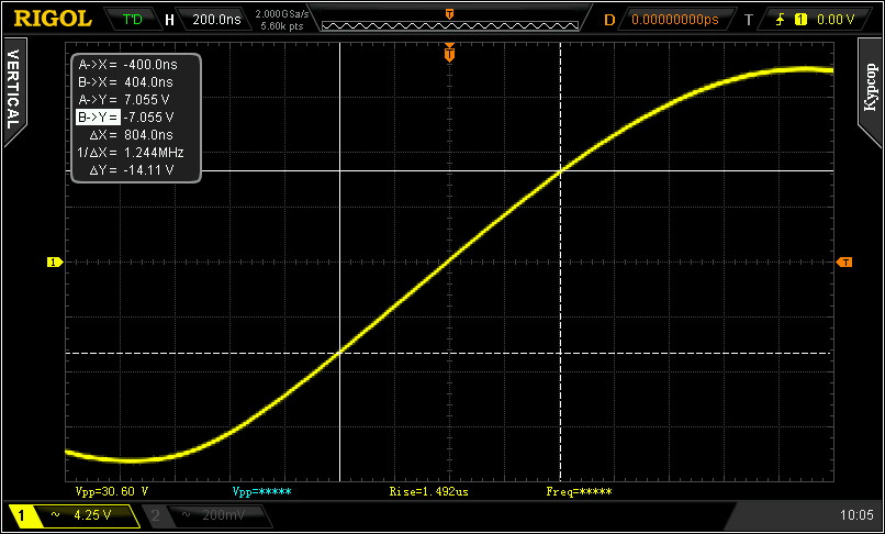
For this purpose, another method of measuring the maximum rate of rise of the output voltage is used. A sinusoidal voltage of such amplitude and frequency is put into the input of the amplifier so that the initial part of the sinusoid turns into a straight line because of the limitation of the slew rate.
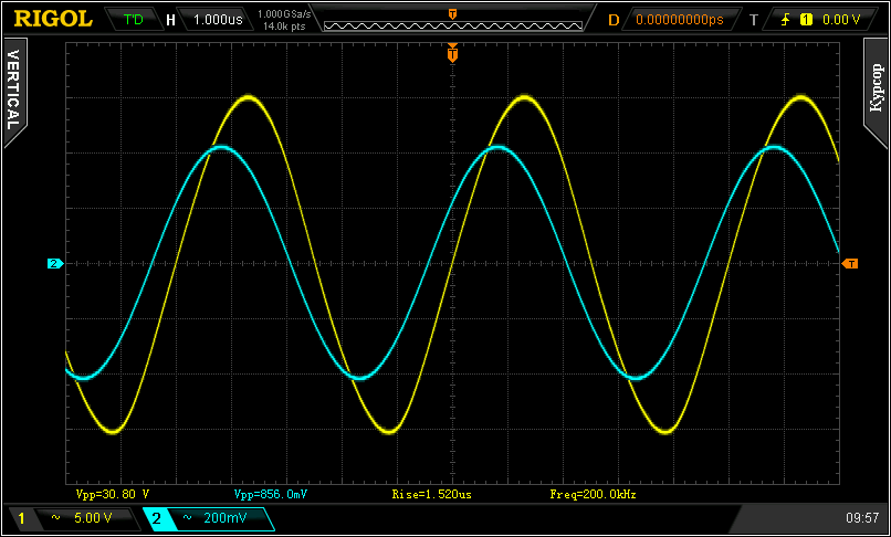
Figure 9 shows the amplifier reproducing a 100 kHz sine wave with an amplitude of about 20 volts (blue is the input, yellow is the output). The sine wave is not distorted, which means that the slew rate of the amplifier is sufficient to handle such a signal.
By the way, this is an output power of 48 watts (4 ohms load) at 100 kHz. Such a slew rate at 20 kHz would give 5 times the output voltage and undistorted power of about 1.2 kW! So this amplifier has good speed capability.
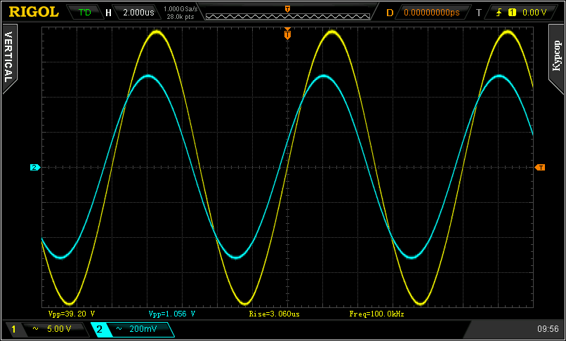
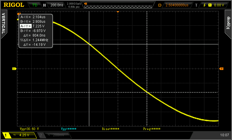
Let’s increase the frequency, Figure 10. Here the central part of the sinusoid (in the vicinity of the zero crossing) began to turn into a straight line. Consequently, slew rate of the amplifier output voltage has reached its maximum. At the same time the distortion of the signal is small, to the eye is not noticeable at all. So we are at the limit, and the overload is about to begin.
The maximum slew rate for the positive and negative half-periods may be different. So let’s measure both. The measurement results are shown in Figures 11 and 12.
The slew rate as the voltage increases:
The slew rate is noticeably slower than for a rectangular signal.
The slew rate with decreasing voltage:
We must use the lowest value. It turns out that the maximum rate of amplifier output voltage rise is 17.5 V/µs.
This method of measurement gives a lower number, it is not so suitable for advertising. But in this mode, there is practically no overloading of the amplifier stages. And if the real slew rate of the amplified signals will not be higher than 17 V/µs, there will be no dynamic distortion. Absolutely. And the sound quality will be high, because the amplifier stages are not overloaded.
In fact, the maximum rate of rise of the output voltage of the amplifier is probably a little higher than I got. According to figures 11 and 12 inside the rectangle limited by the cursors, the oscillogram of the signal is not a straight line. It turns out that I chose too gentle mode and underloaded the amplifier. So in reality the amplifier works a little better than we think it does.
How do you determine if this output voltage slew rate is sufficient for the amplifier? Let’s determine the slew rate required to produce a maximum amplitude and frequency sine waveform.
As the maximum frequency Fmax is usually used the upper frequency of the sound range, equal to 20 kHz. This is wrong. After all, if for some reason a higher frequency with the same amplitude enters the input of the amplifier, the amplifier will be overloaded by the slew rate of the output voltage. It is correct to use the maximum operating frequency, which is the upper cut-off frequency of the amplifier at -3dB, as Fmax. In this case, if the amplifier’s slew rate is sufficient, dynamic distortion will never occur at all!
The reason is this. If the signal frequency increases above the cutoff frequency of the amplifier, the amplitude of the amplifier output will decrease – because above the cutoff frequency, the amplitude decreases. As many times the frequency increases, so does the amplitude decrease. And the rate of amplifier output rise, equal to their product, will remain unchanged. That is, the rate of signal rise above this simply does not exist.
This rule of thumb for determining the maximum required output slew rate is called the “dynamic stability criterion”. If it is satisfied, the amplifier’s power-frequency response (for a signal of maximum amplitude) coincides with the response of the small signal.
Check. The upper 3 dB upper boundary frequency of the amplifier is 50 kHz. The maximum output signal amplitude is 50 volts (with a power supply voltage of about ±70 volts). This corresponds to an output power of 300 watts on a 4 ohm load and 150 watts on an 8 ohm load.
The slew rate of such a sinusoidal signal is:
So, the maximum required slew rate is 15.75 V/µs, and the amplifier provides 17.5 V/µs.
Conclusion: the speed parameters of the amplifier are sufficient, and dynamic distortion will not occur.
In fact, the situation with this amplifier is even better. In this amplifier at high frequencies the AFC decays at a rate of 12 dB/octave, so at frequencies above the upper cutoff frequency the amplitude of the output signal will fall harder and the rate of its rise will also decrease with frequency.
By the way, exactly for the reason that the maximum frequency in the formula is not 20 kHz, but the upper cutoff frequency of the amplifier, the developers reduce this cutoff frequency. There should not be any “AFC down to megahertz”, otherwise the amplifier overdrive in the slew rate becomes possible. Whether it will happen or not is another question, but it will be possible.
Ability to operate the amplifier from a low-voltage power supply
The rated power supply voltage of the amplifier is within ±24 V … ±42 V. This allows the output power to be up to 120…150 W with a 4 ohm load, and up to 100…120 W with an 8 ohm load.
In principle, if the load has a resistance from 16 to 32 ohms, the supply voltage can be increased to a maximum of ±54 volts. In this case, all capacitors in the supply circuit must have a maximum allowable voltage of at least 63 volts, and the output transistors must be well cooled. And the maximum output power will be 200 watts on an 8 ohm load, and up to 110 watts on a 16 ohm load. It is not recommended to work with such supply voltage and 4…6 ohm load – the output transistors may fail.
But when the supply voltage is lowered, not only the maximum output power of any amplifier is reduced, but also the operation deteriorates.
This amplifier is quite well stabilized, so reducing the supply voltage does not catastrophically degrade its performance. The parameters of the amplifier when operating with a low voltage power supply are shown in Figure 13.
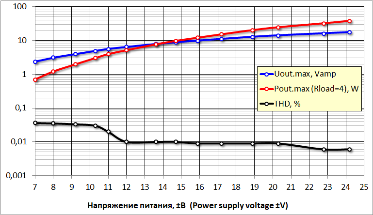
In Figure 13, the blue line is the maximum output voltage with a 4 ohm load, the red line is the maximum output power with a 4 ohm load (the output power with an 8 ohm load is half as much), and the black line is the THD at 1kHz with the output power being approximately equal to the maximum output.
As you can see from the graph, as the supply voltage drops below ±23 volts, the distortion increases slightly. And when the supply voltage drops below ±12 volts, the distortion increases dramatically. But the performance of the amplifier is maintained up to a supply voltage of ±7 volts.
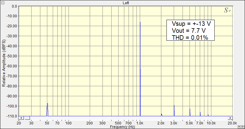
At low supply voltages, not only does the THD increase, but the character of the distortion also changes (deteriorates). Figure 14 shows the harmonic spectrum of this amplifier at a supply voltage of ±7 volts. It clearly shows the even numbered harmonics, which are absent at the nominal supply voltage.
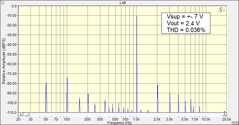
Figure 15 shows the harmonic spectrum of this amplifier at ±13 volts supply voltage. The even numbered harmonics are gone, but the spectrum is wider than with the nominal supply – harmonics up to the 9th are present. With the nominal power supply, the 7th and 9th harmonics are absent.
Even at the lower supply voltage, this amplifier has less distortion than some expensive industrial competitors.
It is important to note that when plotting the graph in Figure 13, the supply voltage was measured under load (that is, with the amplifier running). This voltage already takes into account all possible sags.
Choose component ratings
Choose the output impedance of the amplifier and R21
This amplifier allows you to get as much as a few tens of ohms of output impedance as you desire.
Increasing the output impedance of an amplifier often helps to improve the response of subwoofers and closed-box speakers. By choosing the right impedance, you can reduce the subwoofer’s or speaker’s low frequency response by as much as half. In addition, the increased output impedance of the amplifier reduces the distortion of medium quality speakers.
I do not recommend setting the output resistance of the amplifier higher than 20 ohms, because higher output resistance really does not improve anything, but problems may arise. For example, as the load resistance increases (which depends on the frequency), the output voltage of the amplifier will also increase. And at a relatively low volume, clipping can occur.Or the quality factor of the speaker woofer will increase significantly, and the sound will be “humming”. Or the speaker filters will change their setting (the filters are designed for zero output impedance of the amplifier) and the filters will become unregulated.
The value of the output resistance of the amplifier is set by the resistor R21. You can choose the desired value of its resistance by using the combinOS program, or you can use the graphs in Figures 16 and 17.
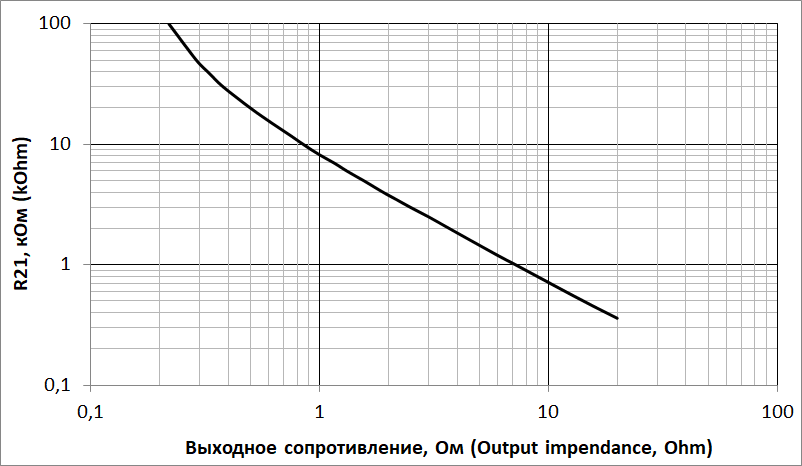
In figure 17 the graph is more extended.
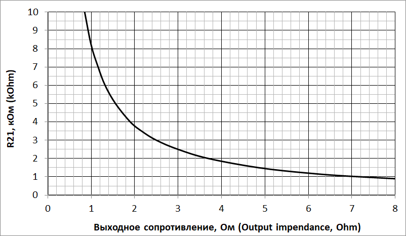
With the R21=20 kOhm shown in the diagram the output resistance of the amplifier will be 0.5 ohms. This output impedance quite often slightly improves the subjective perception of the sound.
If increased output impedance is not required, resistor R21 is not mounted on the board, and resistor R27 is replaced with a wire jumper.
Capacity selection of capacitor C1
The capacity value of the capacitor C1 determines both the lower cutoff frequency of the amplifier and the amplifier’s rolloff at low audio frequencies. This capacitor together with the input impedance of the amplifier forms an high-pass filter (HPF) that passes frequencies above 5…15 Hz and suppresses frequencies below this value.
How the amplitude-frequency response looks like in the low-frequency region at different values of the capacitor C1 is shown in Figure 18.
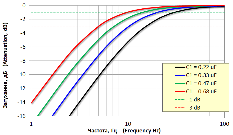
It is convenient to select the values of capacitor C1 from the table.
| Capacitor C1 capacity, μF | Lower boundary frequency of the amplifier at -3 dB, Hz | Lower boundary frequency of the amplifier at -1 dB, Hz | Amplifier frequency response at 20 Hz, dB | Amplifier frequency response at 30 Hz, dB |
| 0,22 | 15 | 30 | 2 | 1 |
| 0,33 | 10 | 20 | 1 | 0,5 |
| 0,47 | 7 | 14 | 0,5 | 0,25 |
| 0,68 | 5 | 10 | 0,26 | 0,11 |
Strategy for selecting the capacitor C1 capacity value.
Before choosing the capacitor C1, remember, what is the lower frequency of your speakers?
- If the amplifier attenuates the signal by 1 dB at this frequency, it won’t be at all noticeable to the ear.
- If the amplifier cuts off the frequencies below the minimum frequency of the speakers, it will only benefit – it will be more difficult to overload the speakers with unworkable for them infrasound frequencies.
The greater the capacitance of C1, the lower the cut-off frequency of the amplifier (that is, the amplifier quite strongly amplifies the lower frequencies), and the less the roll-off of the frequency response at low audio frequencies.
Do we need such low frequencies? Or maybe they are harmful? You can read about that in the article on choosing the input capacitor capacity of the TDA7294 amplifier.
I recommend using a 0.47 µF C1 capacitor for both high-end speakers and subwoofers.
If your loudspeakers go from 30 to 35 Hz, then C1 can have a capacitance of 0.33 μF. If your speakers are operated from 40 to 50 Hz, then C1 can have a capacitance of 0.22 μF.
Capacitance of capacitor C2
The capacitor C2 cuts off the high frequencies coming into the input of the amplifier (it forms a low-pass filter) and thus suppresses high-frequency interference. However, it narrows the operating frequency range of the amplifier in the high frequencies. The capacitance of the capacitor C2 is chosen based on the resistance value of the volume control and the required cutoff frequency of the low-pass filter (LPF), which forms this capacitor together with the resistor R1 and the resistance of the device, to which the input of the amplifier is connected. It may be either a preamplifier with a small output impedance (consider it zero), or a volume control. The resistance of the volume control affects the operation of the filter and must be taken into account.
The cutoff frequency of the input LF filter R1C2 is chosen to be 80 kHz. The same cut off frequency is provided by C7R20 circuit.
The capacity value of capacitor C2 is chosen from the table.
| Resistance of the volume control potentiometer, kOhm | Capacitor C2 capacity, pF |
| There is no volume control on the input of the amplifier, a preamplifier is used | 2000 |
| 5 | 910 |
| 10 | 560 |
| 20 | 330 |
| 30 | 220 |
| 50 | 150 |
| 100 | 75 |
Is it possible to use capacitors C1 and C2 of different capacity?
Yes, they can. A change in capacitance of these capacitors by 10…20% will be completely unnoticeable. If the capacitors’ capacity is changed more, the change of amplifier’s frequency response will probably be noticeable.
If the capacitance changes by more than 30…50%, the following will happen:
Capacitor C1. The AFC in the low frequency range will change. You can estimate this new AFR from Figure 18. If you install capacitor C1=0.33 μF instead of C1=0.68 μF, you will not notice any difference. Similarly, you will not notice any difference if you set C1=2.2 µF. But capacitance C1=0.1 uF on good loudspeakers will be slightly noticeable: amplifier cutoff frequency will be 30 Hz.
Capacitor C2. Decreasing the capacitance will widen the AFC in the high-frequency range, but not by much: the C7 capacitor sets the cut-off frequency of the amplifier at 80 kHz. Increasing the capacitance of C2 improves the filtering of high-frequency interference, but reduces the high-frequency range.
- If the capacitor capacity of C2 is increased 1,5 times, the cutoff frequency of the amplifier will be 40 kHz and the dip of the AFC at 20 kHz will be 0,8 dB.
- If the capacitor C2 is doubled, then the cutoff frequency of the amplifier will be 35 kHz and the dip of the frequency response at 20 kHz will be 1,2 dB.
True, not all people can hear the frequency of 20 kHz, and even more so above…
Choosing Capacitor Capacitance for Subwoofer
If your amplifier is designed for a subwoofer, it is advisable to use these capacitor capacitances:
C1 = 0.47 to 0.68 μF
C2 is ten times the capacitance listed in the table for the amplifier (for capacitance greater than 1000 pF, a lavsan MKT capacitor can be used);
C3 = 220 pF.
Parts used
The amplifier is available for even novice assemblers, but for best performance and to get the best sound possible, quality parts are needed (not necessarily expensive parts): anything that does not work well cannot sound good.
Components from unknown manufacturers and cheap “Chinese” should not be used: it can have poor parameters. And sometimes they are defective at all, for example the resistance of the resistor can differ greatly from the specified one.
But also it is not necessary to chase after expensive special “For Audio” components, because it is not always clear what is meant by this inscription. The fact is that of all types of electronics, audio equipment is “the most undemanding”: it works with fairly simple signals and allows significant distortion. Therefore, a component that cannot be used in other fields (communication, medicine, measurement, space) due to its insufficiently high parameters can be labeled “For Audio” and used in audio engineering – there its weak capabilities will not be noticeable.
So general purpose components from a well-known manufacturer are the best solution. They are for sure functional and have the declared parameters.
Transistors
It is best to use the transistors as shown in the schematic with the exception of VT9.
Transistor VT9 is the temperature sensor of the output transistors. In this position you can use any modern NPN transistor in a TO-126 package. It is not directly soldered into the board, but is wired with minimal length, but such that VT9 can be mounted on one of the output transistors. In the amplifier in figure 1 the transistor VT9 is not in the circuit, but in figure 2 this transistor is present. Also VT9 is shown in Figure 19.
Resistors
The amplifier uses inexpensive metal-film resistors. All resistors except R24…R27 are 0.125…0.25 W. It is recommended that you use a 2W resistor R26. This is more reliable for maximum volume operation.
If a stereo or multi-channel amplifier is planned, the resistors included in the negative feedback circuit (R9, R20, R21) should preferably be used with an accuracy of 1% (you can use more accurate ones, but they are more expensive). In this case, the volume imbalance of the stereo channels will be minimal. If only resistors with 5% accuracy are available, they should be of the same resistance in all channels, if possible. Other resistors are not critical to the accuracy value. However, using resistors R5 and R6 of 1% accuracy can reduce the THD of the amplifier somewhat.
The resistors R24, R25, R27 are SQP wire resistors. You can use wire resistors of other types for the specified resistance and power.
Capacitors
Ceramic Capacitors
C2, C3 and C7 capacitors are ceramic capacitors made of quality low-voltage ceramics, with a maximum operating voltage of 50…100 volts. Quality ceramics are defined by the capacitor’s temperature coefficient of capacitance (TCC). These capacitors should be of the TCC class NP0 or C0G. The manufacturer of the capacitors is important. It is better not to use noname capacitors. Murata, Vishay Epcos, for example, will do.
Film capacitors
Capacitors C1, C8, C10, C11 are lavsan film capacitors (other dielectric names are Mylar, polyester, MKT).
The most important capacitor for the sound is C1. It must be of good quality. A capacitor with a polypropylene dielectric (MKP) can be used at this point. The difference in sound will be small, but it will still be nice that you did the maximum to get a high quality sound. In other positions polypropylene capacitors are not necessary.
In fact, it is much more important to use the right power supply and the right wiring of the amplifier blocks inside the case to get good sound, because the amplifier is a system, and all of its components work for the result. But in any case the capacitor C1 must be of good quality.
Capacitor C10 forms the Zobel circuit. Its maximum operating voltage is 100…250 volts. If there is a choice, it is recommended to choose the largest capacitor available, but without fanaticism, such that it can be properly installed on the board (the maximum distance between the pins is 10 mm). When the amplifier is running, a relatively large high frequency current passes through this capacitor and the capacitor can become hot. The larger the size of the capacitor, the less heat is generated. If you overload with a high frequency signal, though, it is usually R26 that burns out first. We are not talking about audio signals, we are talking about measuring signals. When playing audio with the C10 and R26 elements everything is OK.
Capacitors C8 and C11 help capacitors C9 and C12 supply energy to the amplifier at high frequencies. The capacitance of these capacitors is 0.68…2.2 μF and the maximum operating voltage is at least 63 volts. Capacitors must be of high quality to work well. The more capacitance the better, but be reasonable. It is important that the length of the leads of these capacitors be as short as possible – the inductance of long leads will interfere with their operation. Therefore, a smaller capacitor with short leads (which is easy to install in the board) will work better than a capacitor of higher capacity but with long leads.
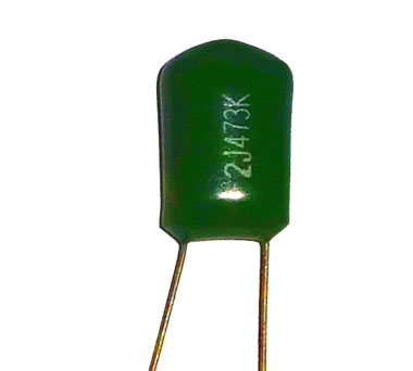
“Green” capacitors (Fig. 20) can be used in positions C8 and C11. Just be sure of their maximum operating voltage.
Electrolytic capacitors
Positions C5 and C6 should have normal quality capacitors. It is possible to use LowESR capacitors, but this will improve so little that it is impossible to detect.
The C9 and C12 capacitors have three functions at once:
- They additionally suppress supply voltage ripple.
- They supply power to the amplifier at volume peaks. These capacitors are mounted close to the output transistors, and the conductors coming from these capacitors are short with low resistance and inductance. As a result, all of the energy from these capacitors is transferred through the output transistors to the loudspeakers.
- They pass through the loudspeaker current at mid and high frequencies. As a result, this current is shorted in the shortest possible way.
All of these functions are actually combined. Physically, they are one function. I separate them in mind, to make it easier to analyze them.
The functions of capacitors C9 and C12 are important, so these capacitors must be of good quality. You can use Low ESR, Low Impedance type capacitors in this position, but be prudent. The importance of the quality of C9 and C12 capacitors is often exaggerated. General purpose capacitors from a reliable manufacturer are better than For Audio capacitors from a questionable manufacturer.
It is not recommended to use C9 and C12 capacitors with a capacity less than 1000 µF. It is also not recommended to significantly increase their capacitance.
Maximum voltage of capacitors C5, C6, C9, C12 must be at least 10…20% higher than maximum supply voltage:
- operating voltage of 50 volts at supply voltages up to 42…45 volts,
- operating voltage of 63 volts at supply voltages of up to 45…56 volts.
Using a polar capacitor as C4
The C4 capacitor creates one hundred percent NFB in DC and minimizes the DC bias voltage at the amplifier output. It is highly desirable to use a non-polar (bipolar) capacitor in this position. The quality of this capacitor is important, but not critical: if it is not possible to use a non-polar capacitor from a good manufacturer, a non-polar noname capacitor is not recommended. In this case you can use a good manufacturer’s polar capacitor with a diameter of 10 mm: 220 μF 50…63 volts, or 470 μF 50 volts. The higher the capacitance and operating voltage of the polar capacitor, the better.
If you do not have experience and measurement capability, the polarity of C4 can be any – it does not matter where you connect the plus of the capacitor and where you connect the minus.
If you have experience and measurement capability, you can orient the polar capacitor C4 when you install it to get the correct voltage polarity on it. To do this:
- When assembling the amplifier, do not solder the C4 capacitor into the board, but “tack” it to the contact pads so as not to fill the solder holes for the capacitor (but securely). The polarity of the capacitor connection is arbitrary.
- Turn on the amplifier, and set the quiescent current of the output transistors at the level at which the amplifier will be operated (this process is described below). Wait for the output transistors to warm up. The output transistors should be set to the radiators with which they will operate.
- Measure the polarity of the voltage at C4.
- Turn the amplifier off, and solder C4 onto the board according to the polarity you measured.
Be careful and watch out!
Amplifier Design
The board dimensions and mounting dimensions are shown in Figure 21.
The output transistors slightly protrude beyond the board, so the board can be installed either perpendicular or parallel to the heat sink, accordingly shaped output transistor pins.
The mounting holes for 3 mm screws are isolated from the circuit.
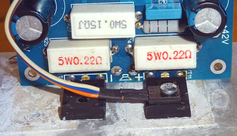
Output transistors are installed on the heat sink (Fig. 22) with an area of at least 1000 … 1500 cm2. Transistors must be necessarily insulated from the heat sink with mica pads (as in the photo), or a special insulating heat conducting film. The thermal paste is placed both between the gasket and the heat sink and between the transistor and the gasket.
Transistor VT9 is mounted directly on one of the output transistors. It is very good if thermal paste is used. If the VT9 has a metallized body (like the recommended 2SD669), then the VT9 body should be insulated from the heatsink, which is automatically done when the VT9 is mounted on the output transistor. The thermal paste ensures good temperature contact.
A metal case is recommended for the amplifier; then there will be a minimum of interference, and the amplifier can fully demonstrate its quality.
Wiring the volume control and blocks inside the amplifier
If you do not have a preamp, the volume control is connected directly to the amplifier, as shown in Figure 23. In this case, it is important that the input circuits and jacks have no contact with ground or the amplifier box.
It is recommended to use a variable resistor (potentiometer) with a resistance of 30 … 50 kOhm as a regulator. The resistance limits of the volume regulator are 5…100 kOhm, but at that a slight deterioration of sound quality is possible: low-impedance resistor loads the signal source, high-impedance one is more sensitive to interference and stray capacitances.
It is better to use a variable resistor with an exponential dependence of resistance on the angle of rotation. Then, when you turn the knob, the volume will change in proportion to the angle of rotation. Such variable resistors have the letter A in their designation.
It is very important to connect the amplifier blocks correctly. Otherwise you can get a very bad sound. Even spontaneous oscillations can occur in the amplifier. There is no magic in connecting the blocks correctly, it is pure physics. For a detailed description see the my article Connecting the Blocks Inside the Amplifier.
Power supply for your amplifier
An amplifier is very much dependent on its power supply for its performance. In fact, the amplifier transfers energy from the power supply to the speakers. But it does so under the control of the audio signal. The power transfer is done so that the signal in the speakers is exactly the same as the input of the amplifier. But if there is not enough energy in the power supply, even the best amplifier in the world will not be able to transfer energy that is not there to the speakers.
A schematic of the power supply is shown in Figure 24. This is a basic circuit which can be modified to suit your needs and/or capabilities. It is not a given, but the result of proper technical design and calculation.
Assignment of parts, their parameters and possible changes
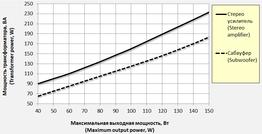
The power of the transformer is chosen from the graph in Figure 25. Why the power of the transformer is less than the total output power of the two channels of the amplifier can be read in my articles Calculating the power supply of the amplifier and Transformer to power the amplifier.
A smaller wattage transformer is not recommended. A higher wattage transformer can be used. But it is also not recommended to increase the transformer power by more than 2 times: There will be no additional benefit, but the interference can increase because the charging current of the storage capacitors is too high and too short.
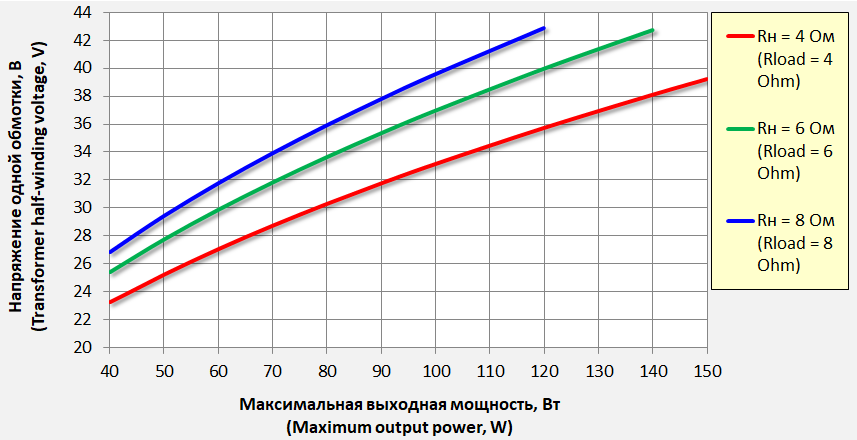
The required voltage on each of the transformer half-windings can be determined from the graphs in Figure 26.
S1 is the power switch. Anything you like, rated for 220 volts and a current of at least 2…3 amps.
F1 is a fuse. It is a must. If your amplifier is up to 60W you get 1 amp, 60 to 100W you get 1.5 amps, over 100W you get 2 amps. If the fuse blows when the amplifier’s power is turned on, the rating should be increased. But not by much – a fuse that is too coarse may not blow in an accident. It is better to use a softstart to limit the inrush current of the amplifier.
C1 is a special interference suppression capacitor (X-type). In addition to suppressing high-frequency noise coming from the mains, it performs two other functions:
- Suppresses noise coming from the amplifier into the line.
- Suppresses self-induction voltage surges of transformer windings, which can occur when rectifier diodes close. Usually the transformer’s own capacitance handles this task, but not always. Especially often such voltage peaks occur when using a high-power transformer, high-speed diodes and a high-capacity storage capacitor at the same time.
VD1-VD4 are rectifier diodes designed for a current of at least 12 amps and a voltage of at least 120 volts. These can be individual diodes or a diode bridge. Schottky diodes give good results. Using high speed diodes makes no sense.
It also makes no sense to use two separate rectifier bridges for each of the rectifier poles.
Using separate power supplies for each of the channels will give little noticeable gain, and the power supply design is much more complicated.
You can include a 0.01 µF 160…250 V capacitor in parallel to each of the rectifier diodes. This usually reduces the interference, both coming from the mains and radiated from the power supply. There is no harm in this (if not to the point of absurdity). Here it is important firstly to mount the capacitors as close as possible to the diodes and to keep the leads as short as possible. Secondly, this solution works the better, the more the capacitors have the same capacity. Capacitors of different capacitance will not do any good.
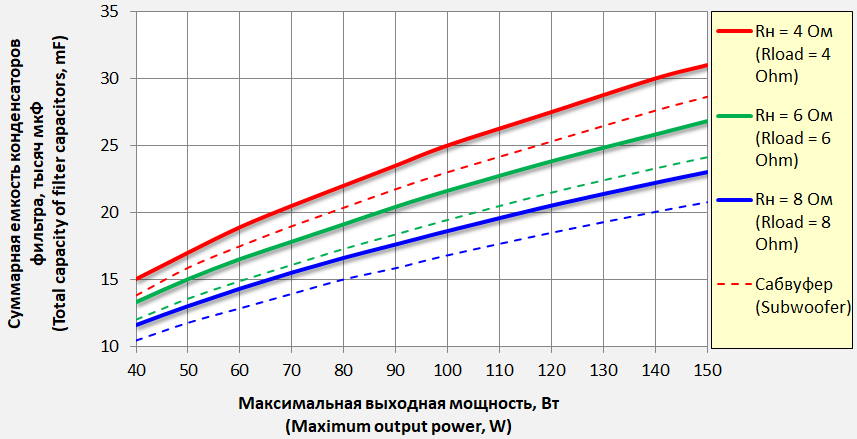
C2 to C5 are storage capacitors. Their capacitance is chosen from the graphs in Figure 27. In fact, the capacitance values in these graphs are rather relative. The amplifier normally works even with a significant deviation of the capacitance of the filter capacitors from the values shown in the figure. But nevertheless, the indicated capacitance values are optimal enough, so that with such capacitors the amplifier works perfectly in any situation.
The number of capacitors in each arm depends on the total capacitance required and on the capacitance available. And also on the design features of the power supply (how much space is allocated for it in the case). Usually 1…4 capacitors are installed in each pole.
It does not make sense to use arrays of small capacitors.
It is not necessary to use a LowESR or LowImpedance capacitor – their resistance reduction will be absorbed by the resistance of the wires connecting the power supply to the amplifier.
R1, R2 are resistors that discharge the storage capacitors when the power supply is turned off. They are optional. Resistance is 68k … 100k. Power is 0,125 … 0,5 W.
R3 connects the circuit ground to the amplifier case. This should be the only connection point between the circuit and the case. Optional. The resistor is needed so that if the circuit is shorted to the chassis, it will burn out and break the connection. You can tell by the fact that the resistor has burned out that a short has occurred.
A good result is the use of an input noise filter. Not “audiophile” but technically correct. With a varistor and inductance coils. Sometimes such a filter is built into the mains wire connector.
It is also a good idea to install a ferrite on the power cord. A ferrite is one of the few devices that can do no harm. That is why ferrits can be installed on all amplifier cables.
If you plan to get 80 watts or more per channel of stereo amplifier power, I recommend using a softstart to ensure that the amplifier starts smoothly when the power is turned on.
Setting up the amplifier
Setting up the amplifier comes down to setting the quiescent current of the output transistors with the trimmer R16. If R16 is set according to the figure on the circuit board, turning it counterclockwise reduces the quiescent current and turning it clockwise increases the quiescent current. Just like turning the volume knob to the right makes it larger, to the left makes it smaller.
The optimum quiescent current of this type of output transistors is 250 (200…300) mA. This current corresponds to operation in the quiescent mode, when the sound signal is not played.
It is set as follows:
1. the trimmer R16 is set to the leftmost position corresponding to the minimum quiescent current.
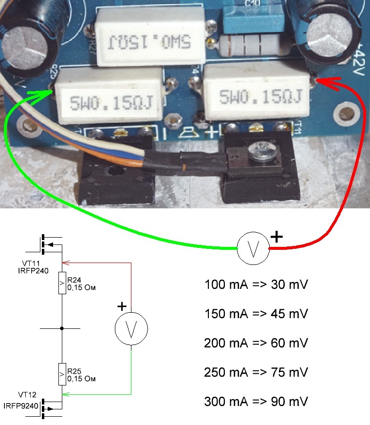
2. A DC voltmeter is connected to resistors R24 and R25, as shown in Figure 28.
3. the trimmer R16 sets the quiescent current to about 300 mA.
4. In some time, when the output transistors are warmed up and the heat sinks are warmed up, the quiescent current will decrease and it should be set to 300 mA again.
5. After some more time, when transistors and radiators finally warmed up, you should adjust current to 200…250mA.
All these operations are done with the amplifier fully assembled.
If there is no possibility to use big radiators, the quiescent current can be reduced to 100 mA. Further reductions in quiescent current (60 mA minimum) will increase distortion in the output stage. These distortions will be partially suppressed by negative feedback. Therefore, with a low quiescent current the sound quality will be slightly lower. Whether you notice it by ear, I don’t know.
23.08.2020